4. Relational Model
The Relational Database Model
Section titled “The Relational Database Model”The relational data model was developed in 1970 by the mathematician E. F. Codd and described using set theory. It remains the foundation for relational databases to this day. Database systems based on this model are still the most widely used form of database systems.
For relational databases, the data manipulation language SQL was developed, which has established itself as an international standard.
In the relational model, a database consists of a set of relations in which logically related data is stored.
Relation
Section titled “Relation”In a relational database, the term relation refers to a set of tuples (records). A relation can be represented as a table with columns and rows.
Both entities and relationships from the Entity-Relationship Model are mapped as relations in the relational model. In database terms, “relation” therefore does not mean the link between tables, but the table itself in which the data is stored. This data represents the information managed in the database.
A relation is characterized by:
- a unique name, e.g.,
Customer - several attributes (columns)
- zero to any number of tuples (table rows or records)
- exactly one value per attribute in a tuple (table cell)
- a primary key, consisting of one or more attributes
- which uniquely identifies each tuple
Attributes and Tuples
Section titled “Attributes and Tuples”A table in a relational database consists of columns and rows. The columns are called attributes or fields, and the rows are called tuples or records.

The structure of all tuples in a table is the same.
The structure of a relation is called the schema of the table. The totality of all relation schemas in a database is called the schema of the database.
Different database systems use slightly different formats for relations. These differences depend among other things on:
- the rules for naming relations and attributes
- the available data types for attributes.
Each data type is assigned certain properties that determine what kind of values can be stored in an attribute (e.g., integers, strings, date values). This means that every entry in an attribute must satisfy the defined data type and therefore also uses the storage space provided for this data type.
NULL Values
Section titled “NULL Values”If no value has been entered for an attribute, a so-called NULL value can be used. A NULL value belongs to no data type and must not be confused with the numeric value 0.
A NULL value is a symbolic placeholder indicating that no value is present for this attribute in a tuple. Since it is only a symbol, a NULL value cannot be compared with any other value — not even with another NULL value.
An empty value is distinct from this: it arises, for example, when an existing attribute value is deleted. Thus, an empty value in a text attribute is an empty string (""), in a numeric attribute the value 0.
In a relation, due to the set definition, no two identical tuples may occur. This means: each tuple can be uniquely identified by one or more attribute values (in the extreme case, by all of them).
The set of attributes with which a tuple can be uniquely determined is called a candidate key. For keys, the minimality requirement applies: A key should be as short as possible; no subset of the attributes used should itself already be a key.
Primary Key
Section titled “Primary Key”From the existing candidate keys, exactly one is selected as the primary key. In an example with the relation Customer, the attribute CustomerNo could be the primary key, because it is the “shortest” possible key (only one attribute). In many representations, the primary key is indicated by underlining (e.g., ER diagrams in Chen or Crow’s Foot notation).
To uniquely distinguish all tuples in a relation, an additional attribute can be introduced that simply numbers the records sequentially. This attribute can then serve as the primary key. This is then called a surrogate key.
Important points about the primary key:
- A relation has exactly one primary key.
- The primary key can consist of a single attribute or a combination of attributes.
- The attribute or combination of attributes used as the primary key is called the identifying attribute (or identifying attributes).
- All attributes or attribute combinations that provide unique values are candidate keys — but only one of them is actually designated as the primary key.
- If a table has no naturally unique data field, an artificial unique ID is often assigned, e.g., an ID for the relation
Customers.
In notations, a primary key can be indicated, for example, by:
- Underlining the attribute name
- the abbreviation PK or
- a trailing character such as
*

Foreign Key
Section titled “Foreign Key”A foreign key is an attribute in a relation that refers to a key field of another relation, thereby establishing a relationship between the two relations.
In notations, a foreign key can be indicated, for example, by:
- the abbreviation FK or
- a trailing character such as
#

Secondary Key
Section titled “Secondary Key”The term secondary key is not clearly defined.
It is often understood as an alternative search key that serves as an additional search criterion alongside the primary key. It can be used to find one or more records. Like any search key, a secondary key can also consist of one or more attributes.
Unlike the primary key, a secondary key in this definition is not necessarily unique. A search with a secondary key can therefore return multiple records as a result.
Another view equates secondary keys with alternate keys, i.e., further candidate keys. In this case, a secondary key is also unique, but is not used as the primary key.
What they have in common is that a secondary key, like the primary key, can also be used to access records.
Often the tuples of a relation are needed in a different order than they were originally stored — for example, sorted by postal code. To do this, the entire relation would have to be sorted by this attribute. With a large number of tuples, this can take a lot of time.
To speed up access to the data, additional indexes can be created alongside the primary key. These are also called secondary indexes or secondary keys.
When multiple indexes are used, a high overhead arises when inserting many records, because all indexes must be continuously updated. In such cases, it is often sensible to create or update the indexes only after populating the table.
An index is comparable to a glossary at the end of a book: terms are sorted alphabetically with page numbers, so that you can quickly find the desired information without having to search the entire book.
Transformation from ER Model to Relational Model
Section titled “Transformation from ER Model to Relational Model”The transformation of an ER model into a relational model is done by mapping entities, attributes, and relationships into relations (tables). The following steps are observed:
-
Convert entity types into relations: Each entity type in the ER model becomes its own relation (table). The attributes of the entity become the attributes of the relation.
-
Define primary keys: A primary key is defined for each relation, which uniquely identifies the tuples. This can be a single attribute or a combination of attributes.
-
Map 1:1 relationships: For 1:1 relationships, the primary key of one of the participating relations can be adopted as a foreign key in the other relation.
 Fig. 7.4: For a 1:1 relation, the primary key of one relation is adopted as a foreign key in the other relation.
 -
Map 1:n relationships: For 1:n relationships, the primary key of the “1” side is adopted as a foreign key on the “n” side.
 Fig. 7.5: For a 1:n relation, the primary key of the '1' side is adopted as a foreign key on the 'n' side.
 -
Map n:m relationships: For n:m relationships, a new relation (junction table, also called a bridge or pivot table) is created that contains the primary keys of the two participating relations as foreign keys. These foreign keys together form the primary key of the new relation.
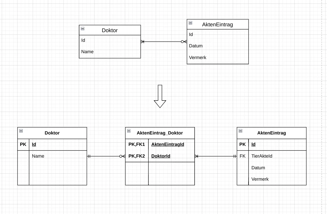 Fig. 7.6: For an m:n relation, a new relation is created that contains the primary keys of the participating relations as foreign keys.
 -
Generalizations: The entity type of the generalization can either a) be fully integrated into the superclass, b) be mapped as completely independent relations each, or c) be represented as a separate relation with a foreign key to the superclass.
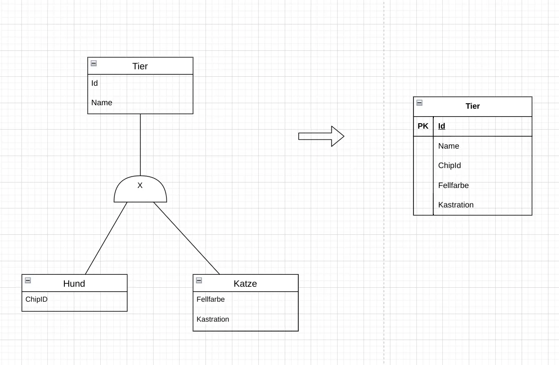 Fig. 7.7: Mapping a generalization in the relational model: creating a single all-encompassing superclass. The specializations are not mapped as their own relations. The superclass contains all attributes of all specializations. Where these are not set, NULL values are entered.
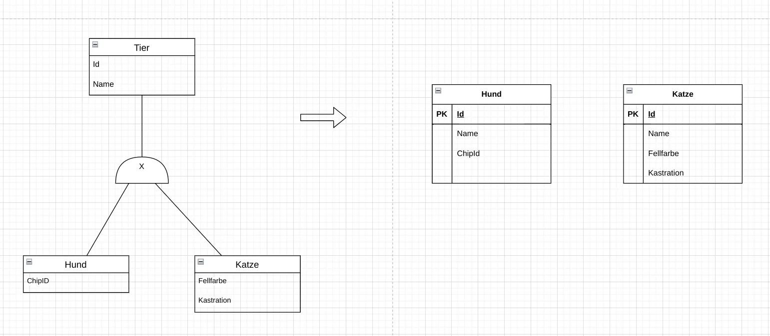 Fig. 7.8: Mapping a generalization in the relational model: completely independent relations. The superclass is not mapped as its own relation; it only exists in the logical ER model. There is then also no information about belonging to a specialization. All attributes of the superclass are repeated in each specialization.
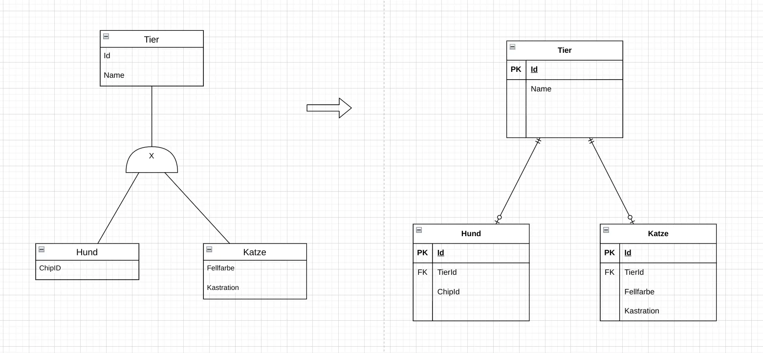 Fig. 7.9: Mapping a generalization in the relational model: one superclass and the specializations with foreign keys. This is the most natural mapping. The superclass is mapped as its own relation, as are the specializations. In the specializations, the primary key of the superclass is adopted as a foreign key. However, more effort is required for access, as the data from multiple relations must be combined (JOIN).
Which of the three approaches is chosen depends on the requirements of the database. Different approaches can also be used for different generalizations within the same implementation.
The transformation from the ER model to the relational model is an important step in the development of relational databases. It ensures that the logical structure of the database meets the application’s requirements and enables efficient storage and retrieval of data.
From the relational model, the physical database structures can then be derived, which are implemented in a concrete database system.
Textual Description of the Data Model
Section titled “Textual Description of the Data Model”A relational database can also be described textually. For each relation, the name of the relation, the attributes with data types and constraints, as well as the primary and foreign keys are specified. Primary keys and foreign keys are explicitly marked. For primary keys, the abbreviation PK is often used; for foreign keys, the abbreviation FK. Alternatively, other markings can be used, such as underlining or special symbols like arrows pointing to the source table of a foreign key.
There are no fixed rules for this notation. What matters is that the description is clear and understandable and contains all necessary information to understand the structure of the database.
Closing Note
Section titled “Closing Note”Learning Outcomes: What you should be able to do after this chapter
Section titled “Learning Outcomes: What you should be able to do after this chapter”After completing this chapter, students should be able to:
- Define: define the terms relation, attribute, tuple, primary key and foreign key.
- Describe: describe the meaning of NULL values and keys in the relational model.
- Explain: explain how relationships are represented via foreign keys.
- Apply: transform an ER model into a relational model following the transformation rules.
- Evaluate: assess which attributes are suitable as candidate keys.